
Below is a list of some of the TinyPICO shields & add-on boards we make
We’ll be adding more as time goes on, so check back every now and then to see what’s new!
TINY Pinout Comparison Matrix

All TinyPICO shields are compatible with the TinyS2 and TinyS3.
RTC Logger Shield
RTC Logger Shield for the TinyPICO, TinyS2 & TinyS3
This shield includes an ultra low powered and super accurate RTC matched with a uSD Card reader and 2x STEMMA/QT connectors with separate IO for 2x I2C channels, or 1x I2C and 1x UART.
The RTC Logger Shield includes the following features:
RV-3028-C7 ultra low power, super accurate RTC that communicates via I2C
Micro SD Card slot
2x STEMMA/QT connectors with 2 sets of IO - Can be used for I2C devices or UART or anything else you feel like
I2C1 on the usual I2C pins for the Tiny board you are using
I2C2 on 2 alternative IO pins for the Tiny board you are using
JST PH connector for easy battery connection
On board button connected to the EVI pin of the RTC that you can program to use as an RTC wakeup or to trigger an event
RTC Interrupt pin is connected to an RTCIO pin on the Tiny board, so you can wake your board from deep sleep with the Alarm
RTC Interrupt pin can be disconnected to it’s IO by cutting the trace on a solder jumper on the back of the board
RTC Clock output is disconnected from its IO pin by default, but you can connect it if you want to use this RTC function by soldering a bridge across the solder jumper on the back of the shield. Left disconnected it frees up the IO for other uses


I2S Audio Shield
I2S Audio Amplifier Shield for the TinyPICO, TinyS2 & TinyS3
This shield takes standard I2S digital audio input from your TinyPICO or TinyS2 and decodes it into an analog audio signal as well as amplifying it for use with an external speaker.
The I2S Audio Shield brings the noise with:
MAX98357 I2S Decoder and Amp
3W Class D Amplifier
I2S sample rates from 8kHz to 96kHz
Click + Pop suppression
Thermal shutdown protection
Micro SD Card slot
Magnetic buzzer for onboard audio via a PAM8301 amplifier
A switch to swap between on-board sound and external speaker that can be connected via provided header
Comes with a separate screw terminal that can be soldered on for external speaker connection
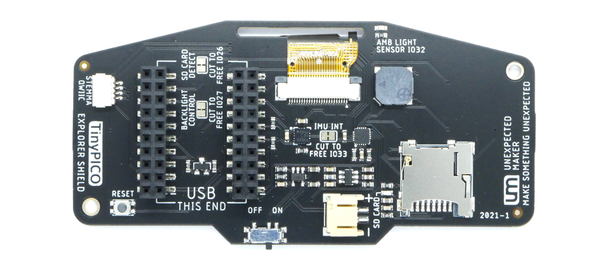
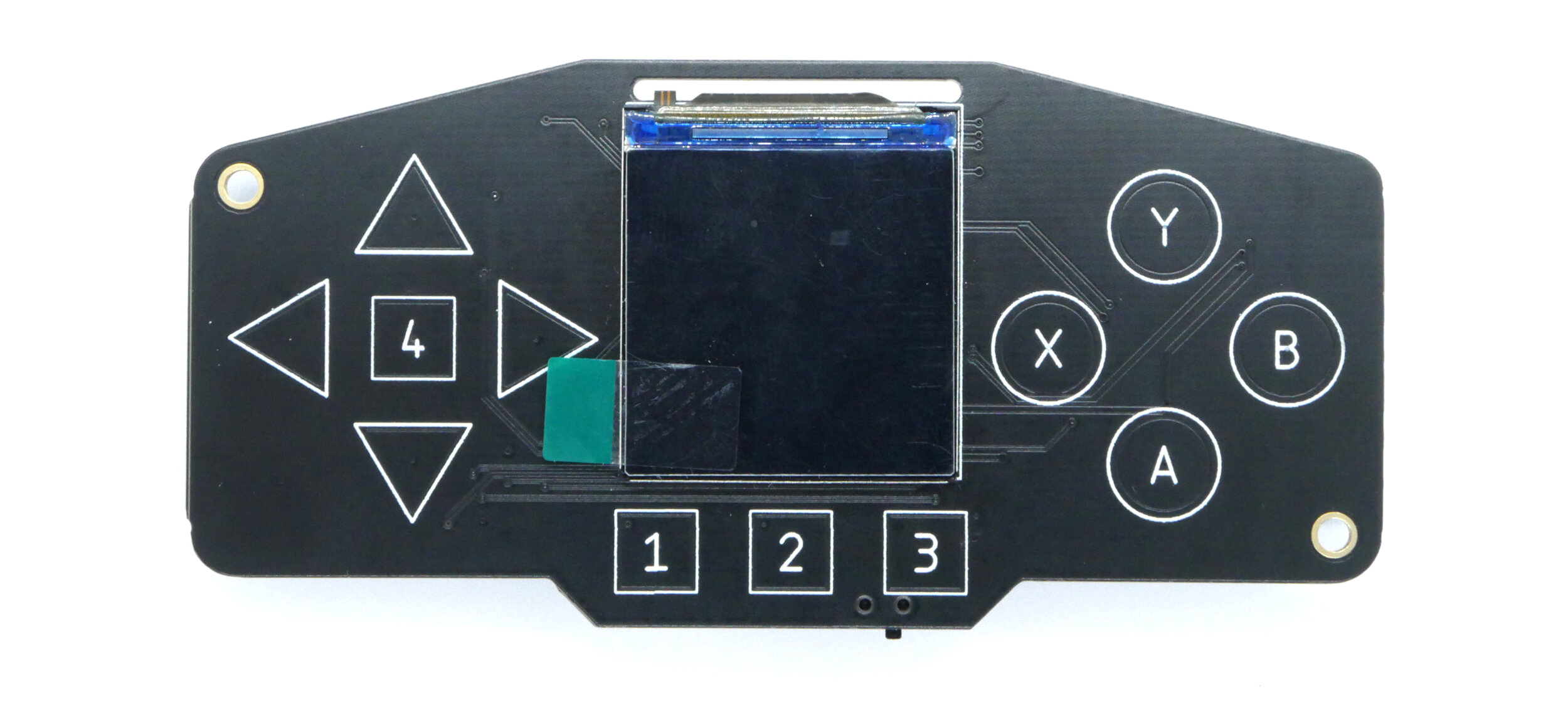
Explorer Shield
The Explorer Shield was designed to be a multi-purpose board that can be used for all sorts of activities like prototyping output, experimentation, and even games. It has lots of goodies on it, including:
240x240 RGB LCD display (ST7789)
12 Capacitive touch buttons (MPR121)
Micro SD card slot
3-axis accelerometer (LIS3DH)
Light sensor (ALS-PT19-315)
Mono audio (PAM8301)
Reset button
STEMMA/QWIIC connector
LiPo connector plus power switch
Headers for your TinyPICO, TinyS2 or TinyS3 with 20 pins broken out in a second row
Some of the GPIO that are used for things like the IMU Interrupt and SD Card detect etc have solder jumper pads that can be cut if you don’t need that functionality, and would like to use that IO for something else.
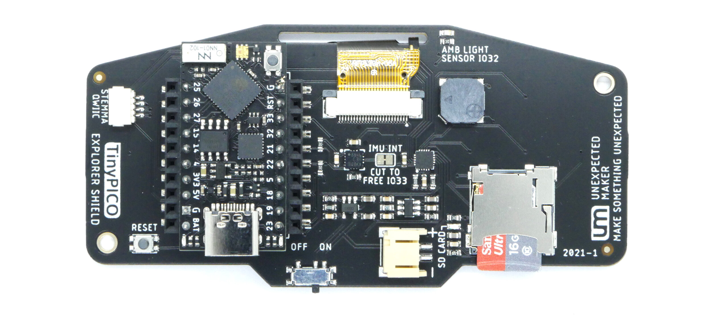
Header pin compatibility
The Explorer shield is compatible with the TinyPICO V1 & V2, TinyS2 and the new TinyS3. The TinyPICO format has 20 header pins, 10 on each side. The TinyS2 and TinyS3 both have 23 pins, 11 on one side and 12 on the other.
To insert a TinyS2 or TinyS3 into the Explorer shield, you connect your board with the USB end aligned, and then let the extra 3 pins hang over the edge of the pin headers on the shield.
Powering from battery
If you power the Explorer Shield and TinyPICO/TinyS2 from the shield JST connector, you can use the slide switch on the shield to power down everything. Make sure you have the switch turned on, if you want to charge the battery when the USB cable is plugged in.
code & platform support
Developing demo projects and libraries specific for the Explorer shield is an ongoing project. The aim is to have Arduino, MicroPython and CircuitPython (TinyS2/TinyS3) projects available over time, but all platforms have libraries that support all of the features of the Explorer shield currently available, so you can hit the ground running with full peripheral support right away.
For now, Arduino users can find an Arduino Template Project on the TinyPICO github repository.
I2C Breakout Shield
The I2C Breakout shield offers 2 sets of STEMMA/QWIIC connectors and pin headers in 2 different 3V3 power rails.
The first has 3V3 power always on.
The second has user controlled 3V3 power that is off by default, so when you put your ESP32 into deep sleep, the 3V3 power for the I2C devices on that I2C bus get shut down automatically.
On the back of the board, you have solder jumpers to choose which IO to use for the 3V3 power control.
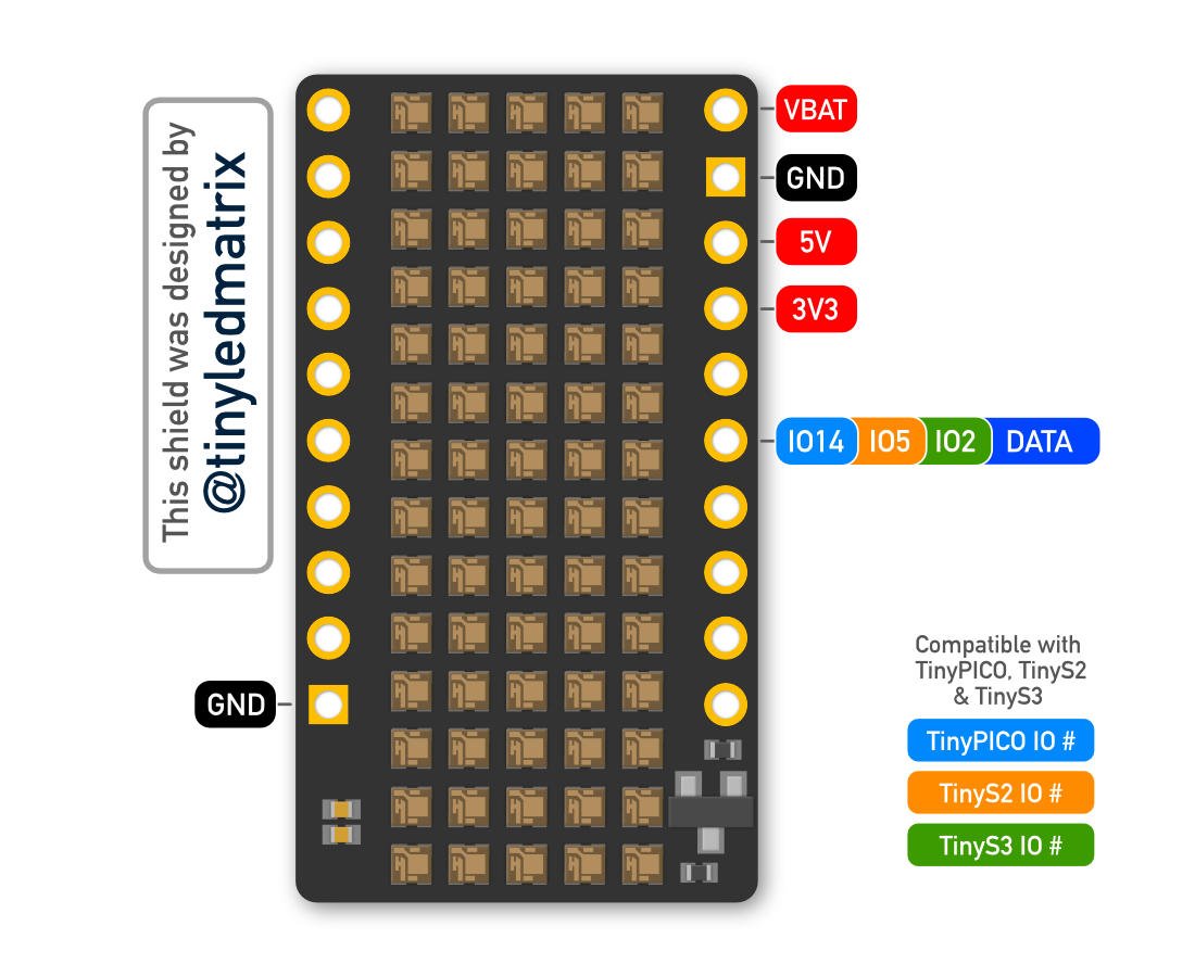
LOL RGB Shield
TThis shield incorporates 70x 1.5 x 1.5mm addressable RGB LEDs into a display matrix that’s so tiny - it lives up to it’s designers name - TINYLEDMATRIX!
The shield requires 5V power to be supplied via the 5V pin of your TinyPICO via USB or external 5V supply, data to the LEDs is controlled by GPIO 14.
You can use any of the Adafruit or FastLED libraries with this shield, but remember, with only 5 pixels height, you need to use one of the smaller fonts.
An Arduino example using the FastLED and Adafruit_GFX libraries can be found on GitHub.
You can also control your LOL RGB Shield via MicroPython using Mike Causer’s awesome library.


RGB IPS Display Shield
This shield has a gorgeous colour IPS LCD display, with a massive 160x80 pixels in a 0.96” form factor.
It uses the ST7735 driver, so there is a lot of library support available for it, but we recommend using the TFT_eSPI library.
If you are using this shield in Arduino land, with the TFT_eSPI library, these are the settings you need to use in your user_setup.h:
#define ST7735_DRIVER
#define TFT_WIDTH  80
#define TFT_HEIGHT 160
#define ST7735_GREENTAB160x80
#define TFT_MISO 19
#define TFT_MOSI 23
#define TFT_SCLK 18
#define TFT_CS   5
#define TFT_DC   15
#define TFT_RST  -1
Please refer to the pinout list above to set the correct IO for your TinyPICO, TinyS2 or TinyS3!
Audio Shield
1.5 W mono amplifier - which can be turned off to reduce power consumption
Magnetic buzzer
Trimmer potentiometer for gain control
A switch to swap between on-board buzzer and external speakers that can be connected via provided header
On the TinyPICO & TinyS2, audio-in is connected to one of the two DACs (Digital to Analog Converter).
The TinyS3 doesn’t have built in DACs any more, but you can still generate cool sounds via PWM.

New Prototype Shields
A selection or prototyping boards for use with the TinyPICO, TinyS2 and TinyS3 microcontrollers from Unexpected Maker.

All prototype boards include:
Low profile SMT headers
Dual row headers for access to all pins on the dev board
JST connector for plugging a 1S LiPo battery
2x STEMMA/QT connectors assigned to different IO
SIDE BY SIDE 3 + PROTO
This prototype board has room for a dev board, 2x shields and includes a large prototyping area with access to 5V, 3V3 and GND
It also breaks out a programming pin header to allow you to attach an external programmer so you can use the native USB (TinyS2 & TinyS3) for non flashing use.
SIDE BY SIDE 3
This prototype board is like the original 3 UP board that shipped with the original TinyPICO, but better!
SIDE BY SIDE 2 + PROTO + CLICK
This prototype board has room for a dev board, a shield and a Mikro Click board. It also includes a large prototyping area with access to 5V, 3V3 and GND
It also breaks out a programming pin header to allow you to attach an external programmer so you can use the native USB (TinyS2 & TinyS3) for non flashing use.
SIDE BY SIDE 2 + PROTO
This prototype board has room for a dev board, a shield and includes a small prototyping area with access to 5V, 3V3 and GND